Views: 100 Author: Tuohai Pump Publish Time: 2022-08-31 Origin: www.txtuohai.com


| |
| |
| |
| |
| |
|
QZB series submersible axial flow pump is a replacement product for the traditional water pump-motor unit.
Because the motor and the water pump are integrated, it can run submerged in the water, which has a series of advantages that the traditional unit cannot match.
The submersible pump is widely used in industrial and agricultural water transportation, urban water supply, light sewage discharge, and water transfer projects.
Submersible axial flow is suitable for low head and large flow occasions. In this regard, it is just the opposite of the submersible sewage pump, the submersible sewage pump is suitable for occasions with high lift and low flow. Both of submersible axial flow pump and submersible sewage pump (Including the submersible sewage cutter pump) can be used in integrated pumping stations.
Since the motor and the pump are integrated, the on-site installation does not require labor-intensive, time-consuming, and complicated axis alignment assembly procedures and the installation is very convenient and fast.
Due to submerged operation, the civil engineering and building structure engineering of the pumping station can be greatly simplified, the installation area can be reduced, and the total engineering cost of the pumping station can be saved by 30-40%.
The submersible axial flow pump runs underwater, the water flows around the motor, the noise is low, and the motor cooling condition is good. It can be built as an underground pumping station to maintain the environmental features of the ground.
The submersible axial flow is easy operation, reliable operation, and convenient maintenance.
The use of submersible axial flow pumps is the most thorough way to solve the problem of building pumping stations and flood control in areas along the river and lakes where the water level fluctuates greatly.
This product implements the standard of JB/T10179-2002 "Axial Flow Francis Submersible Pump".
900QZ–160–110
900: Nominal Discharge Diameter
QZ: Submersible Axial Flow Pump
160: 1/10 of Specific Speed
110: Power of the Pump
Medium type: industrial and agricultural transport water, urban water supply and drainage, mild sewage.
The minimum water level for pumping and discharging: according to the regulations of the product sample, ensure that the requirements for the minimum allowable water level are met.
Cooling of the motor: the pumping medium flows from the outer surface of the motor to directly cool the motor.
Use environment: PH5~9.
Start times: the motor can be started twice in a row when it is cold.
The pump can be started up to 3 times per hour when hot.
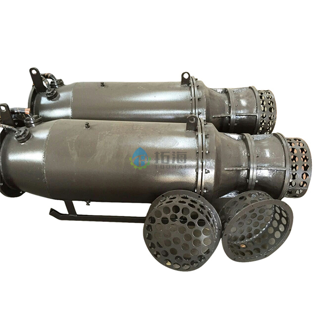
The submersible axial flow pump is a whole composed of a submersible motor and an axial flow pump head sharing a shaft.
The motor and the pump are separated by double or triple mechanical seals, and the cable inlet is sealed with an inlet seal so that the entire motor is in a good sealing state, and the whole machine can run submerged underwater.
The submersible axial flow pump is equipped with protection devices such as leakage and internal winding temperature rise, equipped with a control cabinet, safe and reliable operation, wide adaptability to water quality and environment, adjustable blades, and a large range of head and flow changes. It is a replacement product for traditional pumps.
Viewed from above the motor, the impeller rotates clockwise.
When the motor power is below 315kW, the voltage is 380V.
When the motor power is 280kW to 355kW, the voltage can also be 660V.
When the motor power is above 315kW, the voltage can be 3kV, 6kV, 10kV, and 10kV can be used. The voltage can also be requested by the user.
The submersible motor has a dry structure, the insulation class is F, and the protection class is IP68.
For the high-voltage submersible motor, we have adopted the VPI vacuum pressure dipping process twice and used high-quality insulating materials to make the submersible motor winding as a whole.
Our self-designed grounding system (patented technology) has successfully solved the problem of step high voltage and high voltage leakage.
The motor cooling adopts the cooling technology that has obtained a national patent. The use of three-phase windings has low-temperature rise, uniform temperature field distribution, and high motor operation reliability.
The hydraulic model of the submersible axial flow pump adopts the mature and excellent model designed uniformly across the country, which is interchangeable with the performance of the traditional water pump, which is convenient for users to set the model.
When the semi-adjustable submersible axial flow pump needs to change the working condition, first remove the set screw, then loosen the nut and buckle, and turn the blade, so that the reference line of the blade is aligned with a required angle line on the hub body, and then Install the positioning pin and tighten the nut, so as to achieve the purpose of adjustment (the placement angle of each blade is the same).
Usually when the product leaves the factory. It has been adjusted to a certain angle according to the needs of users.
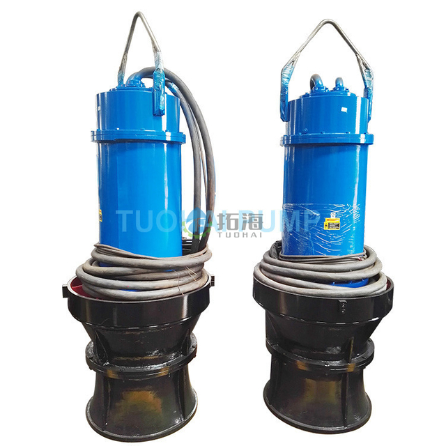
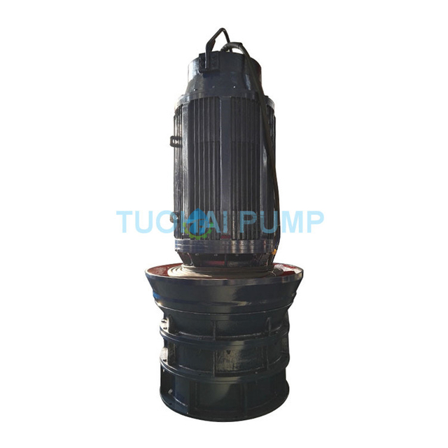
The structure diagram of the vertical type QZ submersible axial flow pump is as follows:
![]()
![]()

1 | Junction box cover | 2 | upper-end cap | 3 | Leakage alarm |
4 | upper bearing | 5 | Thermal protector | 6 | Stator |
7 | Rotor | 8 | Lower bearing | 9 | Leakage alarm |
10 | lower end cap | 11 | upper mechanical seal | 12 | electrode probe |
13 | Lower mechanical seal | 14 | guide vane | 15 | Impeller parts |
16 | Impeller housing | 17 | Inlet horn |
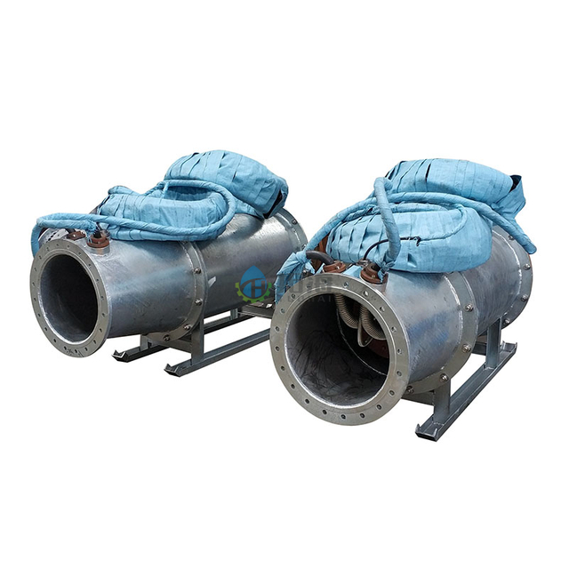
The system includes inlet and outlet water pipe components, cable fixing devices, and cable outlet devices, as shown in the following figure:
![]()
![]()
Electrical wiring connections should be constructed by a qualified electrician in accordance with the electrical wiring diagram and should be performed in accordance with local safety regulations.
Remove the cable head, and then cover it with the terminal block and press it tightly to ensure firmness and reliability, and connect according to the specified wiring method. Pay attention to the parameters on the plate and compare the rated voltage and frequency with the mains voltage and frequency.
In the case of different voltages, the motor cannot be turned on.
The outer sheath of the cable must not have any traces of damage.
The oil-water signal probe (YS) in the guide vane that monitors the mechanical seal on the pump side is checked with a multimeter under normal conditions, and its resistance value is infinite.
The overheating protection probe (WC) monitoring the three-phase winding phase is checked with a multimeter under normal conditions, and its resistance value is zero, that is, the circuit is in a connected state.
The leakage sensor (JS) monitoring the sealing of the cable wiring cavity is checked with a meter in the normal state, and its resistance value is infinite.
The leakage float sensor (XL) monitoring the mechanical seal on the motor side is checked with a multimeter under normal conditions, and its resistance value is infinite.
The shaft temperature sensor (ZW) for monitoring the bearing temperature (the pump above 160kW includes this function) is checked with a multimeter under normal conditions, and its resistance value is zero, that is, the circuit is on.
Wiring of motor power line:
The motor wiring method is "△".
Before the pump is installed, the motor is energized instantaneously in an anhydrous state. Its steering should be in line with the steering signs.
Check the protection of the pump to make sure it is wired correctly.
The rated current of the motor is marked on its nameplate.
Warning:
Must ensure reliable grounding, grounding resistance is less than 4Q
Special reminder: Before installation, please read the warning signs carefully.
The pump is installed on the tapered tube, and an O-ring is used to seal the joint surface of the pump and the tapered tube so that the pump is tightly pressed on the pump seat to obtain a seal.
Turn on the power supply of the water pump instantly on the ground, and observe whether the turning of the water pump is consistent with the turning sign. If it is inconsistent, any two phases of the power supply can be adjusted.
Warning:
Trial operation in water is strictly prohibited, and it will cause serious consequences when reversed in water.
Ensure that the insulation resistance of the electric pump motor to the ground is greater than 50MΩ in the cold state.
Fix the cable fixing rope on the submersible axial flow pump hoisting device with a wire rope clip. When fixing, pay attention to fasten the wire rope clip seat on the working section of the wire rope, and fasten the U-shaped bolt on the tail section of the wire rope. The rope clamp closest to the pump lifting device should be as close as possible to the bend of the wire rope, and the rope clamp farthest from the bend should not be tightened alone.
The wire rope clamps shall not be arranged alternately on the wire rope, and the distance between the two shall be about 100mm.
Use cable clamps to fix the cables on the cable fixing rope, with a distance of 600-700mm. Pay attention to tightening the clamps to prevent the cables from being scratched and cut.
Check whether the connection surfaces of the wellbore are reliable to prevent water leakage from the joint surfaces. Lift the pump into the wellbore. Pay attention to the smooth lifting of the pump. If it is mounted on an anti-rotation block, the pump can be rotated at an angle and lowered.
After placing it, tighten it with a turnbuckle The cable fixing rope is hung on the hoisting ring of the wellbore cross-arm, the cable is drawn from the pressure plate and the flange, the pressure plate is covered and the corresponding sealing is done. At this point, the installation of the pump is completed.
Special Reminder:
The cables cannot be pulled by force, nor can they be used for lifting. to prevent cable and seal breakage.
When the pump is disassembled, it is the opposite of installation. First, lift off the pressure plate, loosen the cable, and remove the cable fixing device when pulling out the pump.
If the cable fixing rope is within 1200mm, no clamp is required.
Test Before Running
Check the insulation resistance of the electric pump motor relative to the ground, measure it with a 500V megohmmeter, the value should not be lower than 2MQ, and check whether the grounding is firm and reliable.
Regularly check the insulation resistance of the electric pump motor relative to the ground, and its value should not be lower than 2 MΩ, otherwise the machine should be disassembled for maintenance, and at the same time, check whether the grounding is reliable and firm, and whether the cable skin is broken, etc.
A certain gap is designed between the impeller blades and the wear-resistant ring, which has a sealing function. When the maximum value of the wear gap in the diameter direction exceeds 2mm, the blades should be replaced.
After the electric pump runs normally under the specified working medium conditions for half a year, check the sealing condition of the sealing chamber and whether the oil in the sealing chamber is in an emulsified state or has water precipitation. If so, replace the L-AN32 engine oil and mechanical seal in time.
When the electric pump is not used for a long time (such as more than 3 months), it should not be immersed in water statically. The standby pump should be replaced regularly to reduce the chance of the motor stator winding being damp. When the temperature is low, the pump should be lifted to prevent freezing.
Fault | Cause Analysis | Solution |
No water from the pump | Wrong direction of rotation | Adjust the rotation direction of the motor, must be tested on the shore, and not allowed to reverse in the water |
Blade fixing failure | Check the blade and impeller seat fixing device, adjust the blade installation angle | |
Insufficient pump flow | The head of the device is higher than the rated head of the pump | Decrease the head of the device or increase the influent water level or reselect the pump type |
Blade placement angle is too small | Readjust the blade angle | |
The speed does not reach the rated value | Eliminate motor failures | |
Vane outer edge wear or vane damage | Replace | |
Valve not open | Check the valve | |
Wellbore installation, cylinder seal is not installed accurately | Re-install | |
If multiple pumps are in common output, there is no check valve installed, or the check valve is not tightly sealed | Check or replace, install check valve | |
Leakage Protection Action | Defective mechanical seal on the motor side | Re-place |
The plug is loose and the water enters | Replace the plug seal, dry the motor | |
O-ring failure and water ingress | Replacing O-rings, drying motor | |
The pump is overloaded or has abnormal noise and vibration | Installation does not meet the requirements | Reinstall according to the installation diagram |
Stop running outside the allowable range (including whether the power supply voltage is within the specified range, the working medium, etc.) | ||
There is debris around the blades, guide vanes, or trash racks | Clear debris | |
Inlet water level is too low, impeller submerged depth is not enough, resulting in cavitation | Pause the operation or reinstall the pump to lower the installation height and increase the inlet water level | |
The blade is installed at the wrong angle or the blade is damaged | Readjust the blade placement angle or replace the blade | |
Bearing damage or lack of oil | Change or add lubricating oil | |
Guide vane water inlet indicator is on | The mechanical seal on the pump side is faulty | Replace the seal, change the oil |
Junction box probe signaling | The inlet sealing cover is not pressed tightly | Squeeze the sealing cap |
Cable broken | Re-place |
Storage
Check the delivered product, as described above, for shipping damage, and check the integrity of each attachment against the delivery record. The pump must be placed vertically in a clean, dry room. The factory has painted butter on the matching parts of parts for protection. If it is stored for a long time (more than 6 months), please maintain it yourself regularly.
Moisture-proof protection
When the product leaves the factory, measures have been taken to seal the end of the cable to prevent moisture. It is strictly forbidden to immerse the cable head in the water.
Mechanical seal protection
The rotor must be rotated more than one or two times a month to form a new protective lubricating film so that the mechanical seals do not stick to each other.
Insulation protection
Water vapor should be prevented from penetrating into the motor barrier from the exposed end of the cable, and the insulation resistance should be low, and the cable end should be sealed during storage.
Note:
The pump should be used under the conditions specified in the factory manual. If the operating conditions are changed, you must negotiate with our company, click here to contact us.